Digital I/O
Project Tree Structure of Digital I/O
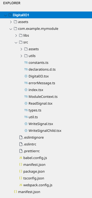
Example of Use
Create Project
We will guide you on how to use the Process Template on Dart-IDE.
Step 1: Open Dart-IDE, click
File‣New Project, and Dart-IDE will show theCREATE NEW PROJECTpopup.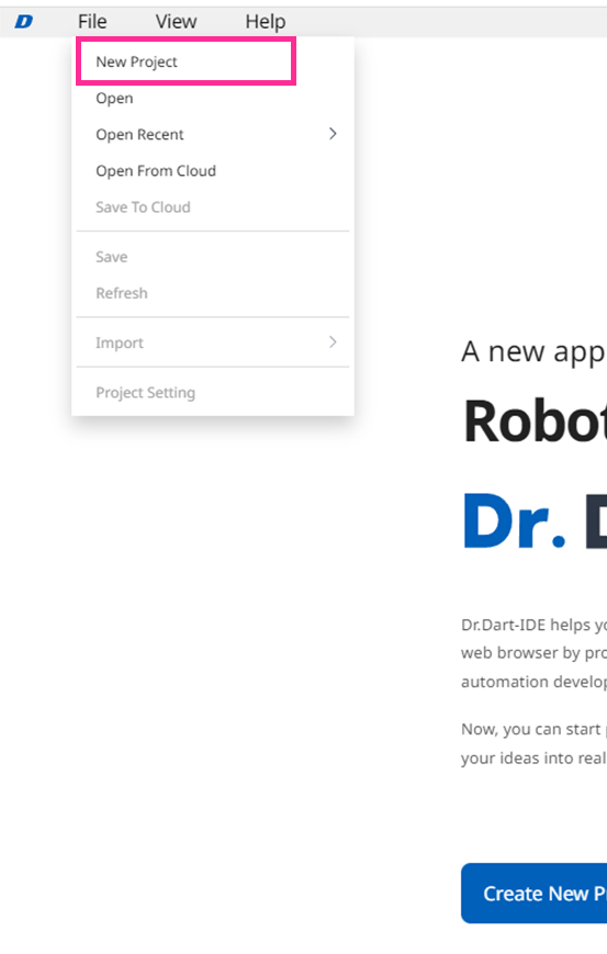
Step 2: On
CREATE NEW PROJECTpopup, click theDigitalIOandNextbuttons. It will show theCREATE NEW PROJECTform.
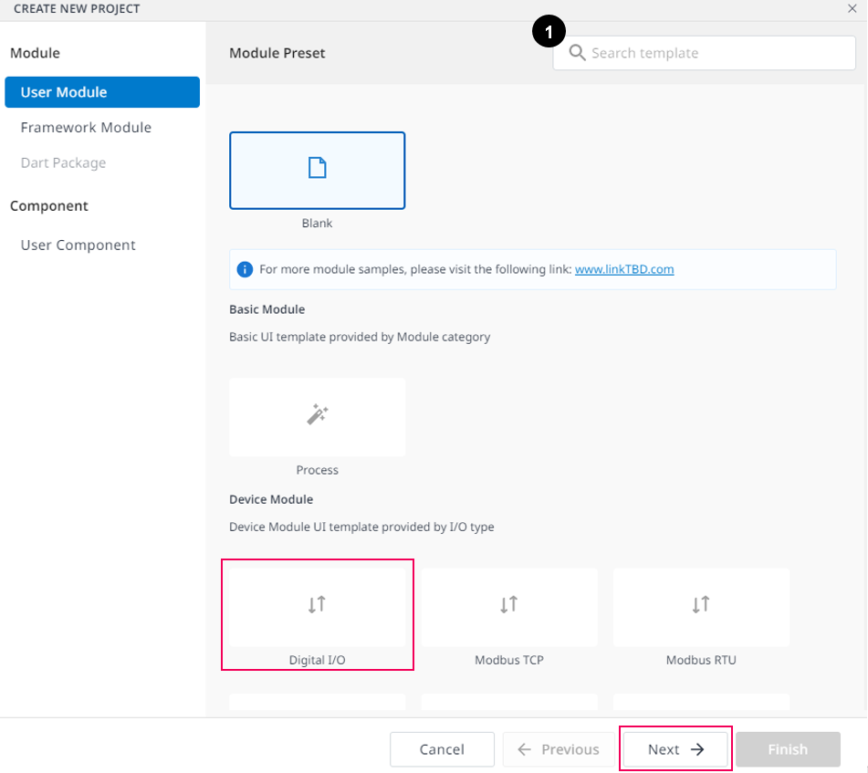
Name | Description | |
|---|---|---|
| 1 | Search | Search the name of the template. |
Step 3: There will be required fields you need to fill in, then click the
Finishbutton.
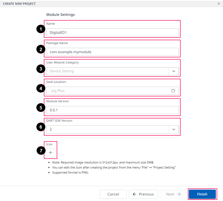
Name | Description | |
|---|---|---|
| 1 | Name | The name of the project. |
| 2 | Package Name | The Package Name of the project. |
| 3 | User Module Category | It defaults. |
| 4 | Save Location | The place where you save your project. |
| 5 | Module Version | The version of your module. |
| 6 | Dart-SDK Version | The list of Dart-SDK versions. |
| 7 | Icon | A thumbnail of the module. |
Step 4: You will be led to the Dart-IDE main screen with your new project with the list of folders and files of
DigitalIO Templateon theEXPLORERpanel.
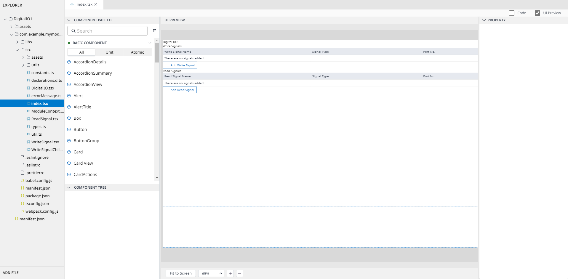
Edit Project
Put the logo on the top
Before editing the project, you have to know exactly the structure of this template and vital tsx files.
Open src, then you have two tsx files to pay attention to.
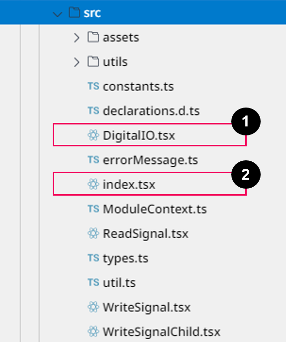
Name | Description | |
|---|---|---|
| 1 | DigitalIO.tsx |
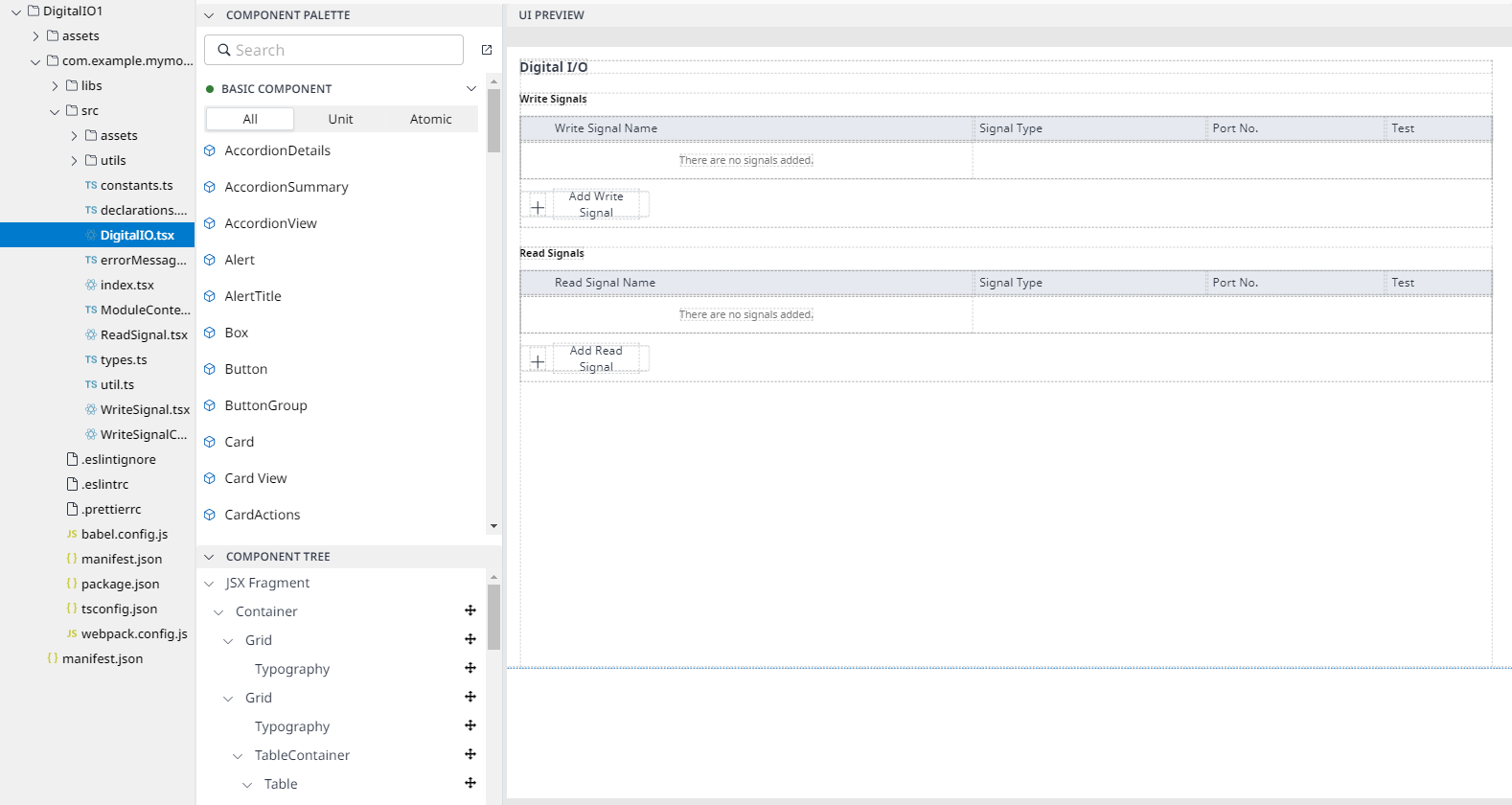 |
| 2 | index.tsx |
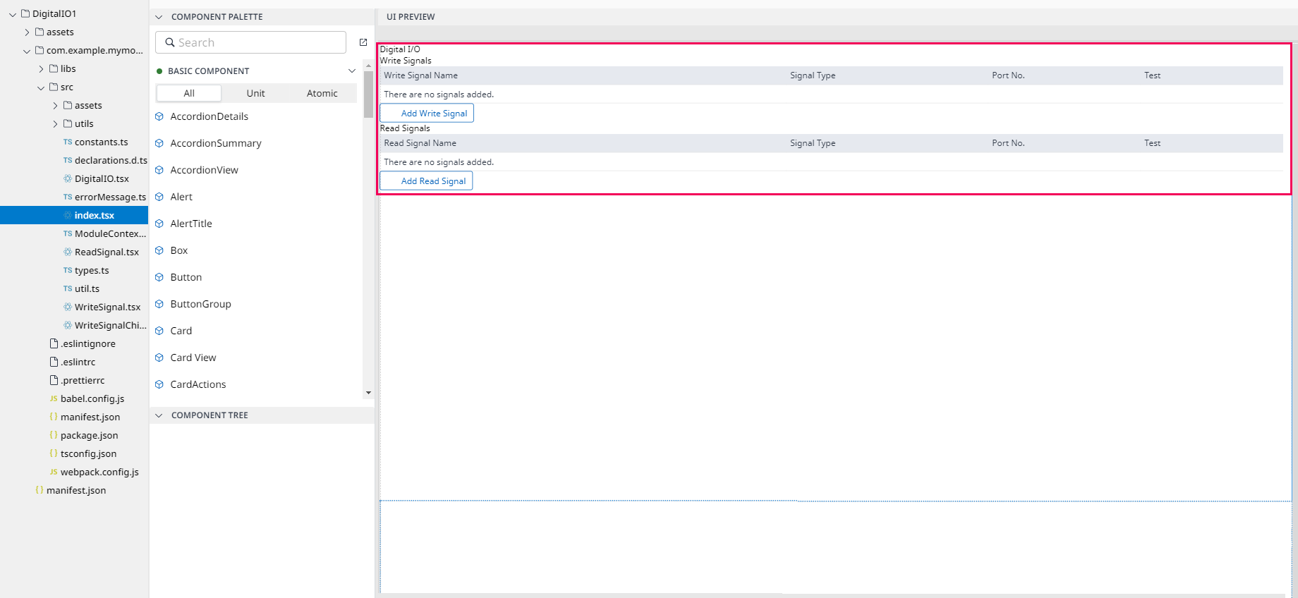 |
Put the logo on the top.
Step 1: Drag & Drop the Image component on the top of the
UI PREVIEWpanel.
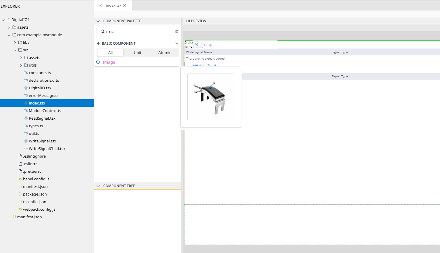

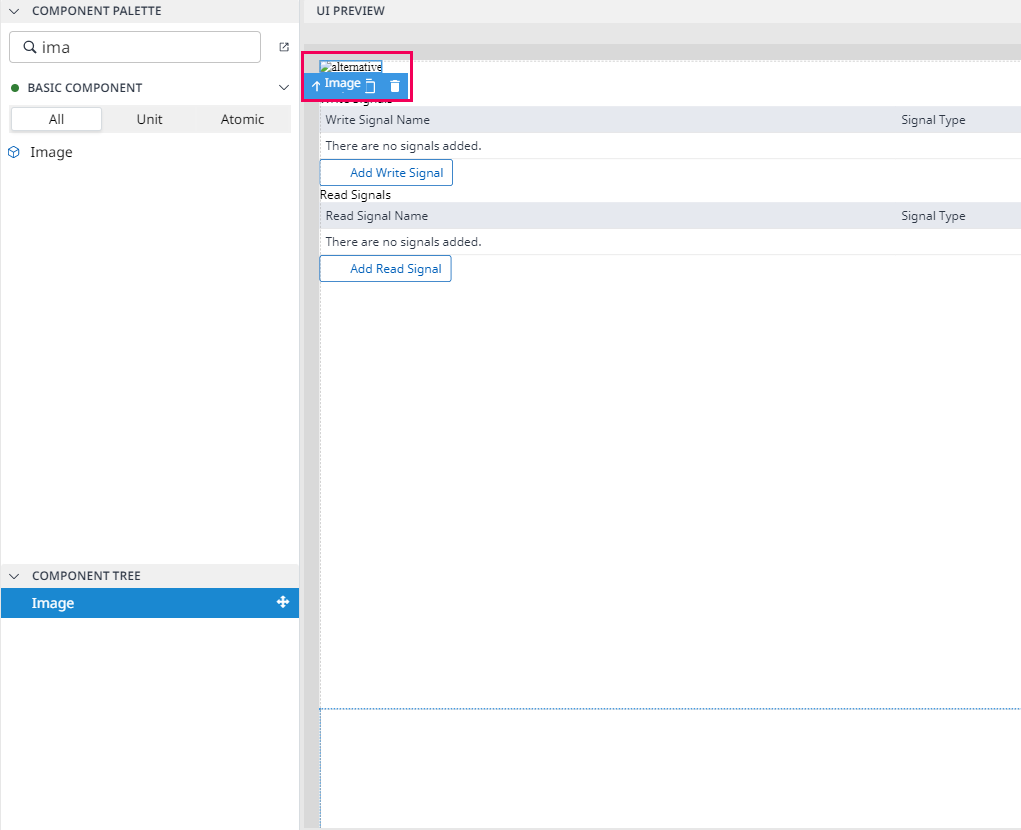
Step 2: On the
PROPERTYpanel, click theSOURCEoption, and then the screen will display like the one below:
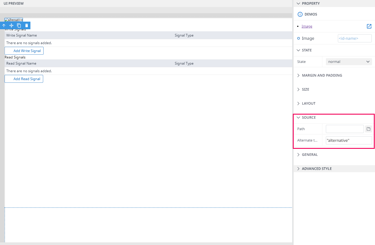
Step 3: Upload your logo by clicking the file icon in
Path.
.png?inst-v=d2d8af3f-8e9b-4ec7-8013-3be7c5999e7f)
Step 4: You can edit the logo to improve it in the
PROPERTYpanel.
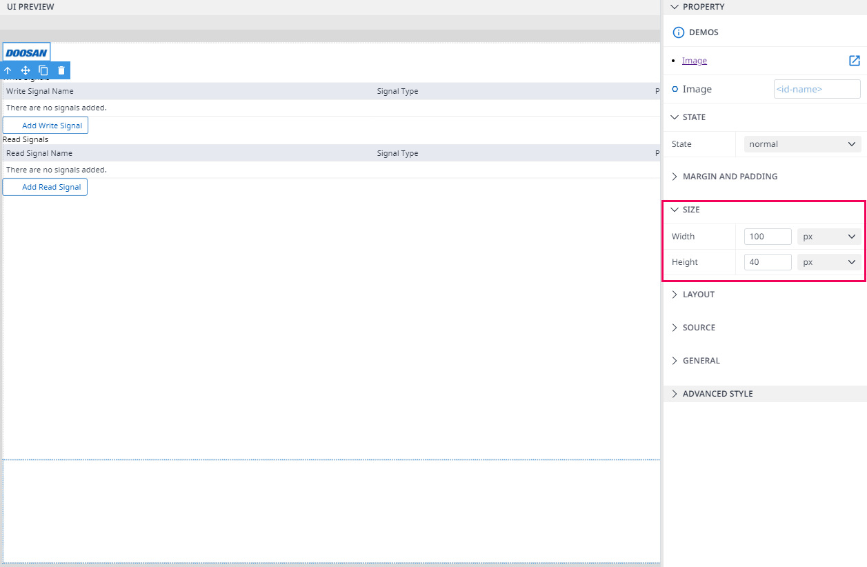
The result is as the one below:
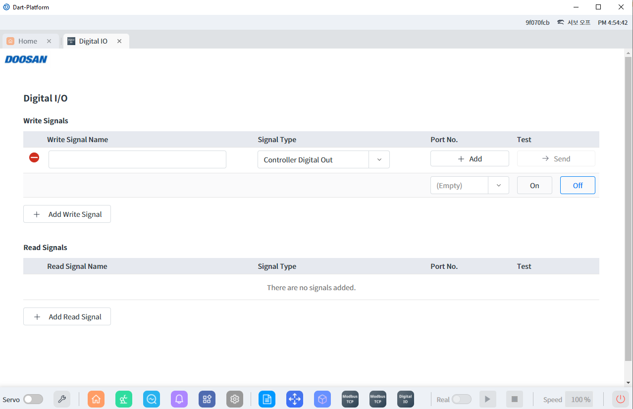
Re-design project (Minor level)
In addition to adding images, you can edit the design by adjusting the component in the PROPERTY panel or adding some components by dragging & dropping to make your project look better.
You can follow the Sample from Section 2 to Section 4 in Create your first Module and apply for your project.
How to use the Digital I/O Module
If you want to use this Digital I/O module, you must prepare the information below:
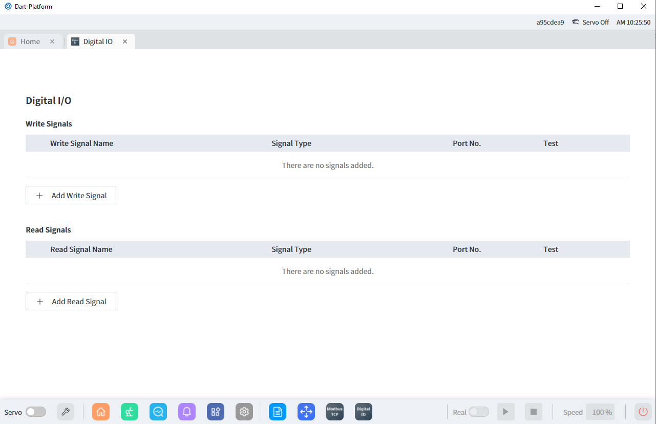
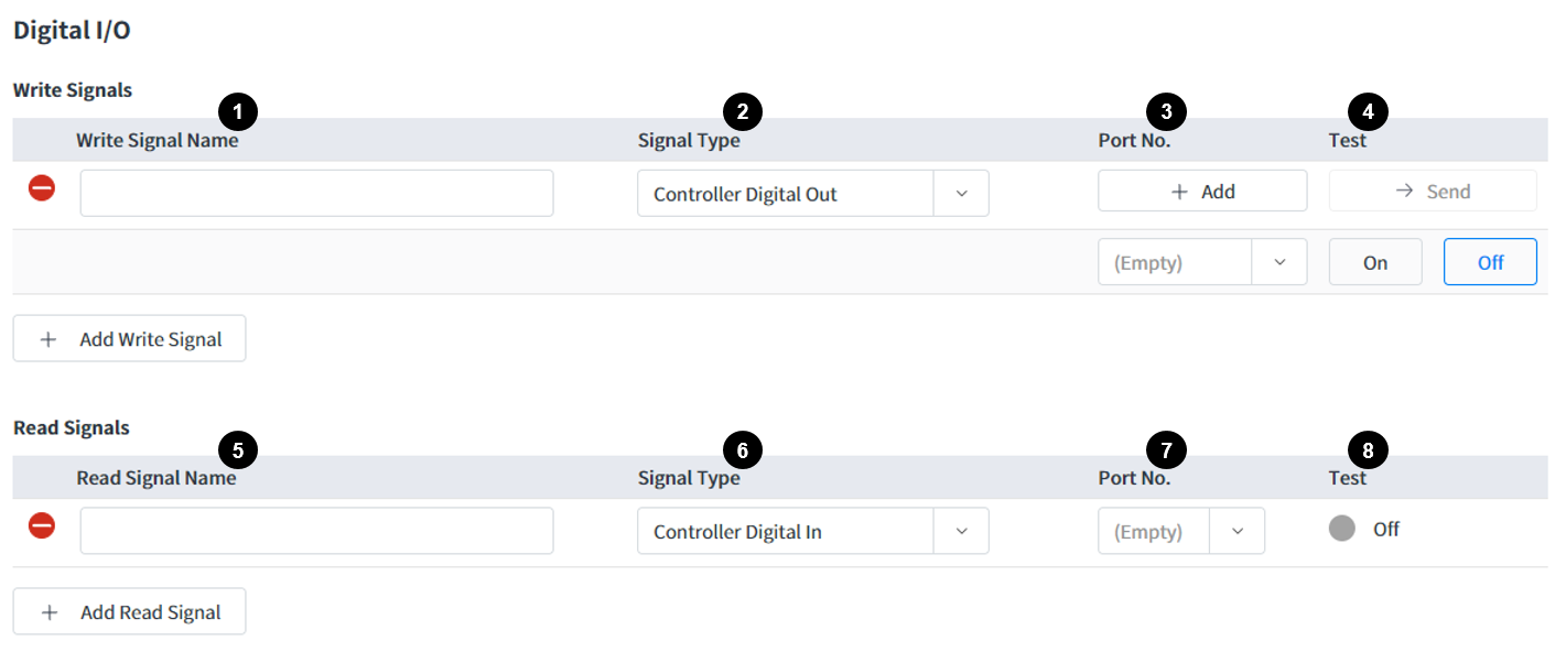
(1) Enter Signal Name.
(2) Choose
Signal Type.(3) Port number list depends on the signal type and robot model.
(4) Show On/Off toggle button.
(5) Enter Signal Name.
(6) Choose
Signal Type.(7) Port number list depends on the signal type and robot model.
(8) Show On/Off status.
Info.
Digital I/O (DIO) stands for "Digital Input/Output". DIO refers to signals that can be either digital inputs or digital outputs in the context of electronics and control systems. A digital input is a signal that is used to represent a binary state (e.g. 0 or 1, on or off), and it is used to detect the state of an external device or sensor. A digital output is a signal that is used to control an external device, such as a relay or a solenoid. DIO signals are used extensively in automation and control systems, such as PLCs (Programmable Logic Controllers) and microcontrollers. These signals are used to monitor and control the state of various devices and systems, and they are often used to trigger events or control the flow of information in a control system.
